Reinforced concrete structural drawings on Mac
How do you go from a finite-element frame model to an engineering drawing dossier? DÈLGHEM exhibits output based on an actual D2 project model: not a single column, but plans, elevations, frame member identifiers and original reinforcement DXF details. These are demonstrator drawings, not signed construction documents.
View the full reinforced concrete drawings ↗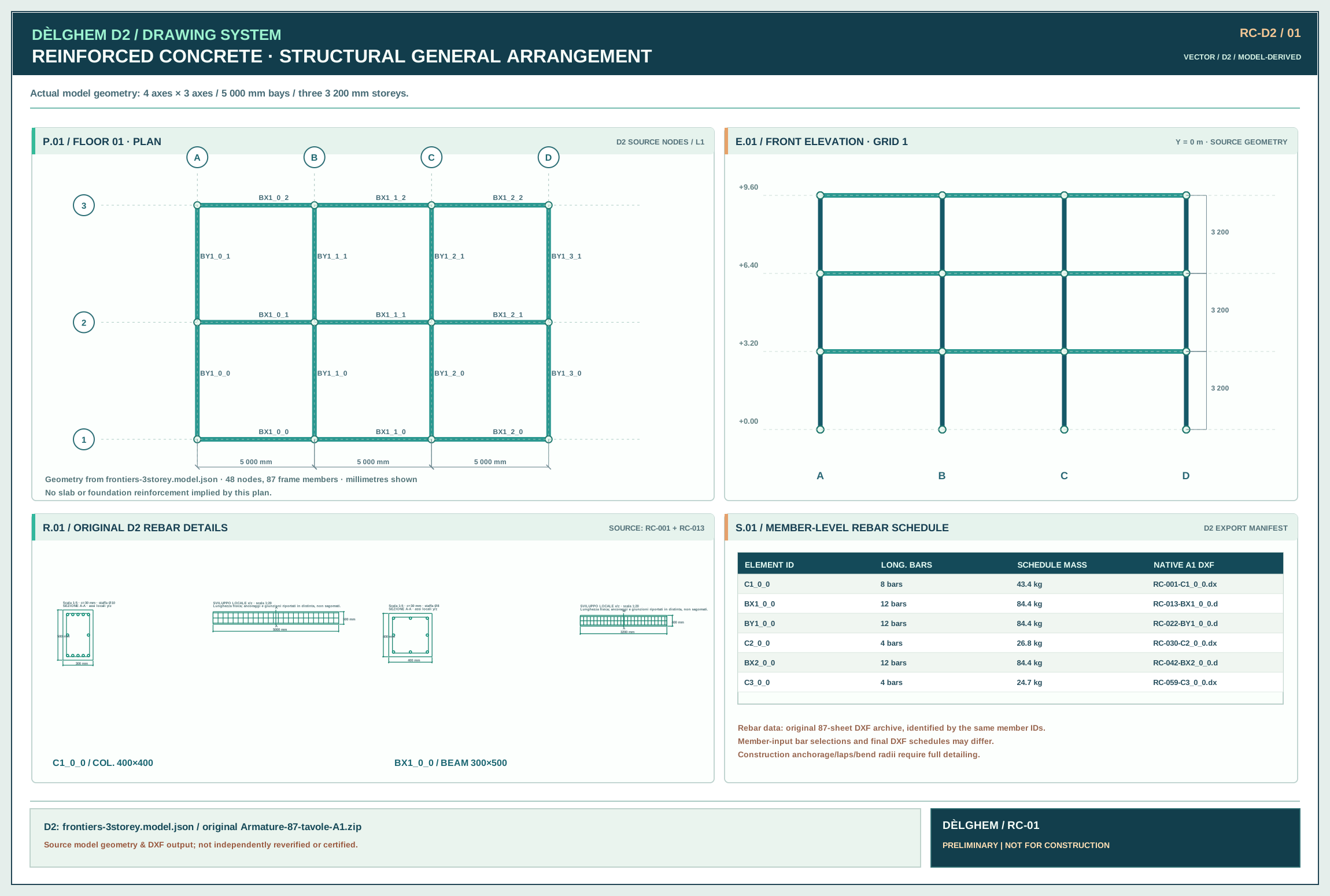
From a D2 structural model to general arrangement drawings
The source is a real three-storey D2 reinforced-concrete benchmark with 48 nodes and 87 one-dimensional members. The plan uses the stored node coordinates: four axes spaced 5 m in one direction, three in the other. The elevation is set at 0, 3.20, 6.40 and 9.60 m. Member references link the general arrangement to the model and its details.
Beam and column reinforcement: sections and schedules
The second drawing sheet brings together six different members with geometry sourced from the application’s actual DXF exports. The original archive contains 87 A1 DXF sheets and a five-sheet PDF preview. Reinforcement schedules report archived bar masses rather than inventing quantities for presentation purposes.
What a construction-ready reinforced concrete set requires
A construction-ready set additionally requires fully checked longitudinal and transverse reinforcement, cover, anchorages, lap lengths, congestion, bends, dimensions and consistency with the structural analysis. The original D2 manifests explicitly state that the drawing batch is not yet a complete executable design.
Why structural context matters as much as each detail
An isolated detail does not explain joint continuity, member locations or the succession of floors. This presentation connects general arrangement drawings with beam and column details, retaining source member IDs while distinguishing overall context from originally exported CAD geometry.
How to audit an engineering drawing against the source model
A practical review begins with the member identifier: locate it on the floor framing plan, then locate the corresponding reinforcement detail in the original DXF batch. The exported IDs are retained in the displayed schedules. BX denotes beams along one axis, BY describes the perpendicular beam family, and C refers to columns in this particular D2 test model. This makes it possible to trace position, section designation and scheduled bars without relying on an attractive but isolated image. This is a document consistency check, not a resistance or serviceability certification.
FEM results and reinforcement design are different deliverables
A finite-element solver provides a displacement and internal-action response for declared material laws, restraints and load cases. To create construction reinforcement drawings, a design workflow must additionally define bar selection, shear and bending resistance, anchorage and lap rules, ductility detailing, joint congestion, bend geometry and traceable bar marks. Numerical analysis alone, including a real Kratos benchmark, cannot establish that those steps have all been completed. DÈLGHEM therefore labels its solver evidence separately from the archived rebar sheets and states clearly which checks remain unfinished.
Frequently asked questions
Are these drawings construction-ready?
No. They are source-derived D2 demonstrations, not a verified and signed construction set.
Can I inspect the original DXFs?
Yes. The drawings section links to the original A1/DXF archive and PDF previews.
Technical material from DÈLGHEM D2 development; software, design outputs and individual checks remain subject to validation. vAlpha1 release planned for January 2027.